


Intro
I spent quite a bit of time trying to design a digitally controlled power supply. I even have some prototypes and three articles, Part 1, Part 2 and Part 3.
One day it hit me: across the years, I built multiple prototypes, spent a lot of time on it and never ended up anywhere. Why? because I did not really need one and I did not have any pressure to build one. So this is a project I will abandon in favor of a purchase.
What to buy?
I did consider some options for purchase. There were some things I wanted
- Minimum 2 + 1 channels
- Digital control and open remote control
- Hobby friendly price
- Reasonable quality, but not pro price
- at least 10mV/1mA resolution
- Nice, modern, color LCD display
- low enough noise
Amongst the options I considered (not necessarily meeting all criteria) were
- Get one of the non-programmable, cheaper analog PSUs.
- GPD-2303S – Review here
- PeakTech 6180 or 6181. No reviews at that moment, but could judge what to expect based on my Peaktech 6225A review
- Siglent SPD3303 – high and low resolution. Review here
- ITECH IT6302 – a OEM version of some more reputable brands. Review here.
- NGE102 if I really stretched the budget and was willing to accept lower power per channel.
- GPP-4323, recently announced.
Why the GPP-4323
There are some particular things that set the GPP-4323 apart. But overall it has some nice functions while it has more features than competitors in the price range. Here are the main reasons I picked it:
- It can fit my price. Note: the 3 and 2 channel models are only slightly cheaper, I really recommend the 4 channel one.
- All four channels are fully controllable, unlike other models which have severely limited aux channels. Here you have two high power (32V, 3A) and the two aux are just lower power(5V/1A, 12V/1A), but are fully programmable and operational as CC/CV, have OVP, OCP, OTP.
- The two main channels can work as a load, which no other models do
- The other models GW Instek makes seem to have good reviews and good quality components.
- Nice display
- Remote control via USB with open API.
The review
On with the review then. Do note: at the time of the testing the firmware was V 1.08, 14.05.2019 and my instruments do not have the best calibration.
It’s also clear that I am not testing everything, as it would take a tremendous effort. I am also not showcasing everything it can do, please see the manual for that.
The looks
There is nothing special to say about it. It broadly looks as you would expect from a lab power supply. Screen looks good and can be viewed from any angle, the buttons feel OK. It feels sturdy and well built, not cheap. Heavy, but not very because it has a toroid transformer.

General behavior
- Fan: runs from the start at low speed. Adjusts in steps as the supply gets hotter or colder. At lowest setting it is a bit louder than my laptop, but barely audible at half a meter away.
- Channel isolation: none of the four channels has any out the outputs connected to earth ground, which is good. Some supplies have one of the auxiliary channels connected directly to earth because they are sharing the supply with the digital part (the display and CPU).
- Buzzer buzzes when needed. I don’t use or like it, so it is turned off.
- LCD light: high pitch sound at low or high setting, so I keep it at max, but it does not bother me.
- Idle power consumption is 15.2 W, turned on, with all channels OFF. Quite significant, I would say.
Accuracy of setting and meters
Lets start with the specs: the setting and metering accuracy is ±(0.03%+10mV) and ±(0.30%+10mA).
First test: check output voltage (unloaded) and displayed voltage for some set values. I took a log approach. The results show a max error of 15mV across all channels and tested voltages. While this is within spec, when looking at how large the errors are at low voltages you see that you cannot trust either the meter or the setting to be anywhere near what you want below about 20mV. The table below labels all xx_delta (the errors of meter or setting) as green as they are within specification. However, I have labelled the CHx_meas (measured) and CHx_disp (displayed) with red where the error is more than 10% of the set value, indicating the supply is not really useful for such small values.

For the current the situation is similar. The 10mA error is in practice smaller, with a max deviation of 4mA. Again, the red labels indicate that you cannot pretty much trust the supply under 5mA.

These results show the supply is within spec, even though it is rather disappointing that the setting and readout errors are so high. Basically this means that the last digit is pretty much useless where it matters, at low values. I cannot say the 10mV error is a problem for me, but the 10mA is, since I cannot measure properly my low power nodes.
Power ON test
I checked what happens when the power supply is switched ON, from the mains switch at the back. None of the 4 channels displays any sort of glitch upon powering on the supply from the main switch.
Soft power ON test, no load.
All channels are set to 5V output.
Setting all channels to 5V and 1A current limit and turning ON: results for CH1 and CH2

Setting the current limit to 3A shows just a small improvement in rise time, therefore this is the start-up speed of the control loop.

Setting the current limit to 10mA gives a good estimation on the output capacitor filter to about 440uF, so probably a 470uF capacitor. There is no improvement on CH1 rise time, therefore that pretty much gives the speed of the supply.

CH3 and CH4 at 1A each

CH3, CH3 at 10mA each indicates about 80uF (so probably 100uF).

Soft power ON test, 10R load
Ch1, CH2 with 1A current limit, so still in constant voltage more. Nice. No overshooting.

Ch1, CH2 with 0.1A limit. Again, excellent behavior.

Ch1, CH2 with 10mA limit. Good behavior, a bit of overshoot.

CH3 and CH4 with 1A current limit

CH3 and CH4 with 0.1A current limit

CH3 and CH4 with 10mA current limit shows a small overshoot of 100mV extra.

Turning OFF, no load
The power supply seems to have an internal R load based on the exponential decay
CH1 and CH2

For CH3 and CH4 the discharge is faster, probably due to smaller capacitor.

Transient tests
Please check all channels. The measurements are different because the channels are different. Sometimes I went in more details on one specific channel.
Channel 1
100mA load, 50% at 10Hz

1A, 50% at 10Hz (current limit is 3A) – no current limiter in action

But here there is trouble

Average current is about 0.5A, confirmed by the multimeter.
But the PSU shows either close to 1A or close to 0A (see picture for 0A) or oscillates between close to 0 or close to 1A (when I choose a frequency like 9Hz). It seems that the meter reads the value at a certain frequency and depending on how the WF generator and the readout aligns, it shows either one of the values. There does not seem to be any averaging or RC filtering of the meter.
1A, 50% at 10Hz, with current limit at 0.5A

The power supply takes about 8ms to drop to the set current limit, during which there is some oscillation. The meter problem is still here. Added bonus, the CC/CV indication flickers as well.
5A, 50% with current limit set at 3A.

Short circuit test,
trying to pull 5A when the current limit is 100mA. Result show that the PSU will provide about 5A current for about 1 ms, probably due to the output capacitor.

Channel 2
Behavior seems to be pretty much the same as channel 1.
100mA load, 50% at 10Hz

Stable output
1A, 50% at 10Hz (current limit is 3A) – no current limiter in action

1A, at 10Hz, with current limit at 0.5A
The power supply takes about 8ms to drop to the set current limit, during which there is some oscillation.

5A, 50% with current limit set at 3A.

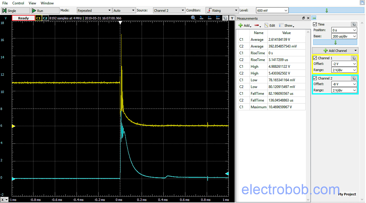
Short circuit test,

trying to pull 5A when the current limit is 100mA. Result show that the PSU will provide about 5A current for about 1 ms, probably due to the output capacitor.
Looking at it in detail shows some oscillations for the first 350us. Also significant overvoltage, towards 15V. Note that this measurement is at the PSU burner side, after two ~1m cables which have their own inductance.

What if I turn the overvoltage protection? It does not seem to catch it! The main reason might be that this high voltage spikes are at the end of the cable, not present at the output of the PSU. A quick scope measurement across the connectors of the psu shows this is not there. So it is important to check where we are measuring.
Channel 3
The current limit is set to 1.1A (max of channel)
100mA load, 50% at

Stable output
1A, 50% at (current limit is 1.1A) – no current limiter in action

1A, 50%, with current limit at 0.5A

The power supply takes about 8ms to drop to the set current limit, during which there is some oscillation.
5A, 50% with current limit set at 1A.

Here we can see that the current can briefly go to 5A, recovering in half a ms. (filter capacitor probably)
Short circuit test,

trying to pull 5A when the current limit is 100mA. Result show that the PSU will provide about 5A current for about 200 us, probably due to the output capacitor.
Seeing it in detail

Channel 4
The current limit is set to 1.1A (max of channel)
100mA load, 50% at

Stable output
1A, 50% at (current limit is 1.1A) – no current limiter in action

1A, 50%, with current limit at 0.5A

The power supply takes about 8ms to drop to the set current limit, during which there is some oscillation.
5A, 50% with current limit set at 1A.

Here we can see that the current can briefly go to 5A, recovering in half a ms. (filter capacitor probably)
Short circuit test,

trying to pull 5A when the current limit is 100mA. Result show that the PSU will provide about 5A current for about 200 us, probably due to the output capacitor.
Seeing it in detail
Load function
CH1 and CH2 can act as a load, up to 50W, or 33V or 3.2A, whichever comes first. They can operate in constant voltage, constant current or constant resistor mode. There are various applications for this: you can test the supply itself, you can discharge a battery (and use the built in monitor function to stop at a certain voltage). Unfortunately the minimum voltage it can pull current from is 1.5V, so no single alkaline/NiCd/NiMH battery test.
It is also easy to test a regulator module. Set it to 3.3V, thinking that the circuit will work with at least 3V. I can test how much current it can supply by using the load in constant voltage mode at 3V. Whether this works depends on many factors, such as the regulator filtering and current limitation strategies.

Here is another test to make and find out why this 5V UPS for raspberry pi could never properly power a Pi for me, not even from USB, let alone battery. Here I started to increase the current until the output either drops below 4.75V or crashes. In this case, it crashes already at 1.7A. So much for the 4A output….

Programming
Clearly an important reason of getting this power supply was the ability to program it. Now, there are three levels of programming, beyond the control of the operating parameters (Voltage, Current, OCP, OVP, series/parallel, load mode etc).
- Basic monitoring: this tells the supply to do something once a condition is reached. This is limited to a simple criteria: something about voltage, current and power, with different thresholds and results, like turning the channel off. This is useful for something like charging/discharging a battery.
- Advanced sequencing: where you define some waveform for the channels. I don’t think i will be using this.
- Full remote control: this I will probably use with computer remote control with scripts. I have use this for a little bit, sending simple commands, but for the moment I do not have an application in mind.
Results summary
Setting and metering
The power supply seems to live up to the specification, which means that:
- The last digit for all setting and metering is useless, considering the 0.03% +10mV and 0.3% + 10mA allowed error.
- It is strange that the offset error is not 10X smaller for current, considering the range is 10X smaller (30V vs 3A, both read with 0.0001 resolution).
- The meter readout is sampled, but there is no filtering. Depending on the current draw waveform you might get a very wrong value (i.e. it can pick the ON or OFF in a PWM load and display that instead of the expected average).
Transient
Transient response is generally good.
- The power supply is not the fastest out there, but it is decent.
- There is no output spike when the main switch is turned on.
- There is no overshooting with and without load when turning on a channel.
- There is no over voltage spike when going from constant current to constant voltage (when a short or load is removed)
- Short circuit response happens in under 300 us for channels 3 and 4 and in under 2ms for channels 1 and 2.
- The meters on the supply are sampled (at 10Hz maybe…) so a variable load produces chaotic reading.
General stuff
- Fan runs at idle from the start, than ramps up in steps
- The LCD brightness at medium or low produces a high frequency buzzin.
- None of the channels are connected to earth ground, they are all isolated.
Programming
- It can be controlled via RS232 (who still uses that?), USB (yes) or with optional Ethernet or GPIB (which I did not get)
- Only played a little bit via USB serial port, seems straightforward to control from scripts, but there is a lot to learn (almost 100 pages in the manual)
- There does not seem to be any remote control software that duplicates the panel on a PC
Noise
Cannot measure the noise at the moment as it is below the input noise of my instruments.
What could be better
- Significant offset in the setting accuracy, i.e. 10mA, even with a 0.1mA set/readout is really bad.
- Higher resolution on the low power channels: using a higher value shunt could yield a better offset
- High pitch noise for backlight setting other than High (PWM too low frequency probably)
- Charge indication during charging/discharging of battery
- Lower load voltage (min is 1.5V).
Teardown
There is no tear-down at the moment. The power supply is still in warranty and I intend to keep it nice and operational. However, you can find some pictures of the insides here.
Pingback: An odd torch – Energizer Pivot – Electro Bob
Thanks for a very in depth review! Currently struggling deciding on PSU’s near this price range. In 2022, besides quirks, how is this holding up for every day needs? Is the electronic load enough for projects? Was thinking of maybe settling on this or possibly settling for something less and buying the additional full fledge electronic load. Curious to know you thoughts if you would choose differently. I love the UI, but I’m not able to find much screen shots interfacing through pc for control, data logging, and programming.
Besides the wonderful screen shots you have loaded* of course. Was referring a video footage to gauge responsiveness and the extent for scripts you can run.
see here https://www.youtube.com/watch?v=xLPfIr-7Q6s
It’s been holding up great. For me the electronic load was enough, often used it to test capability of DC/DC converters. Of course, i am in the range of small electronics. In case you need something with a higher load, its better to get a dedicated one.
Though, I have used it less then expected, I have been having little time to build stuff lately.
Hey, thank you for the review! Is the output on off switching done by a relay or is it semi-conductor based? We have an application which requires frequent on off switching of the channels and relays are loud and tend to die after to many cycles.
It seems to have electronic switching.
But: for channel 1-2 I can hear a relay click during on/off if the set output voltage is set to >7V. I suspect it uses relay to choose a higher transformer tap, which gets activated when you turn the channel on.
Hi,
good review. Are you still satisfied of the power supply?
I thank you.
Steph.
Yes I am. It work great, minus the few quircks mentioned in the review.
Hey Bob,
Many thanks for sharing the test results of your review for the GPP-4323.
Can you share the methods or the example scripts that you’ve used to remotely control the instrument ?
Best regards,
Kostas
Hey Kostas, I did not use any special scripts. Just connect using a terminal and send simple commands like set voltage x, set current x, turn ON etc. These are documented in the manual.