


Check out part 2, where the basil is watered automatically.
Intro
Part of my home automation system is monitoring the well-being of various other non-human species around the house. So i started with the plants. Since they are mostly fixed creatures and generally require only water input from humans, monitoring the soil humidity is a good start.
How
There are quite a few ways to measure how much water is in the soil, some of them described here. But the internet shops are full of cheap soil humidity sensors which don’t work. They are based on measuring the resistance, which due to the current present induces corrosion. Andreas Spiess has a nice video explaining the problem where he also shows the newer type of sensor available. This one:

These sensors measure the moisture of the soil through the use of a capacitor made of PCB tracks. Higher moisture results in higher capacitance which changes the output voltage. The simplified block diagram of the sensor is below, but you can also find another description of the sensor here.

The way it works is this: there is a TLC555 used as an oscillator (passives around omitted) which produces a square wave at around 500 kHz, which has an amplitude almost equal to the power supply of the 555, since this is a rail to rail version. This wave is passed through a low pass filter formed between a resistor and a capacitor made of PCB tracks (R1, C1). This capacitor is moisture dependent, with higher capacitance resulting in a lower pass corner, which results in a more attenuated signal. To produce a DC voltage from that amplitude a simple diode and capacitor rectifier is used (D1, C2, R2).
But why all this you ask? It is quite possible (and products exist) where the soil capacity influences the frequency of the oscillator. You just count the frequency and you are done. But since the capacitor is low value, the frequency will be quite high. This poses a lot of problems to the micro counting it, since it needs to rely on some hardware capture module, which is complicated for Arduino users. As frequency to voltage conversion is more complicated to use on the variety of arduino compatible boards.
What is the problem?
The issues I encountered are probably someone else’s blessing. The sensor is designed to be operated from a supply larger than 3.3V and contains an on board 3.3V LDO which powers the whole circuit. This results in a fixed internal supply and an output which can theoretically go from 0V to 3.3V (the 555 is a rail to rail version and let’s ignore the diode for a while). This makes it easy to supply and interface to something working at 3.3V or 5V which is most platforms of micro-controllers that are mains powered. But…
… the output of the sensor is dependent on the supply of the TLC555 oscillator, which is normally 3.3V, as long as the input is larger than that and the regulator does its job. However, my battery powered sensors are normally supplied by two AA(A) batteries, meaning that a 2 to 3V supply is available. I could, of course make a node taking 3 batteries and use a 3.3V regulator, but where is the fun in that?
Solution
Since the CMOS version 555 on board can operate from 2 to 15V which covers most of the two battery range, could the sensor operate without the regulator? Obviously this means it’s output is dependent on the supply as well, but that is something a microcontroler can know. Enter one de-regulatorized sensor:

On for some tests now. I tested the sensor in two circumstances: dry (just on the desk) and with the capacitor completely submerged in water (no, not coffee), which looked like this:

I then varied the supply between 1.8 and 5V and checked the sensor behaviour. And here it is: the sensor is so finely linear:

That means that once I know the supply, I can determine what output voltage corresponds to a completely dry and completely wet sensor:
Vdry = Vsupply*0.96-0.37
Vwet = Vsupply*0.63-0.7;
The sensor output (0% to 100% moisture) will be between the two lines (red, blue) at any given supply. The high voltage (Vdry) is as expected almost equal to Vsupply minus one diode drop due to the circuit. The low voltage however has a much lower dependence on the supply. Once I know the dry and wet expected ranges of the sensor, everything in between is scaled linearly.
I used one of my 1000² ZEN sensor nodes to get the readout. This is a very tiny version, which attaches on top of a 2xAA battery holder.

To keep low power, the sensor VDD is coming from one of the GPIO pins and will be turned off most of the time. You really don’t need to know the plant humidity more than once per hour. The the exact output from that pin is read by the ADC to monitor the sensor’s supply and used in the calculation. This is needed because the 5mA the sensor draws causes a perceivable drop on the pin driver.
Here is the sensor in-planted in my basil pot

And now, the basil speaks to me:

The first jump (from 0 to 9%) is after the sensor is placed. The second jump is watering the plant in the morning.
Update 29.09.2019
I have tested a few more sensors: 1 which came with the one tested above and another set of 5. The results are interesting and good. Here’s a picture of the sensors with the removed regulators:

And the data. Sensors 1 and 2 are from one lot and manufacturer, 3 to 7 from another.

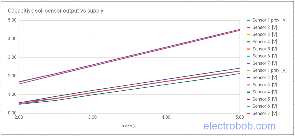
It seems that the sensors are reasonably close to each other, with a clear clustering: the two old and the new 5 are closer to each other. However, I am quite amazed with how close all of them are, in general. While the dry values are closer, the wet ones are more spread apart. Still, I think that I can just use all the sensors without calibration, the biggest concerns when dealing with watering the plants are going to be the types of plants themselves.
Left to do
Come to think of it, a temperature test would be useful to perform.
Pingback: Solar panels for sensor nodes – Electro Bob
Very interesting this sensor! Thanks for the info.
Any idea where to get sensors with TLC555?
Great post.
I’ve picked up quite a few of these sensors and most use the TLC555 but others occasionally use NE555.
This tip works great with the TLC555 which can happily go down to 2V, but unfortunately the NE555 is a 5V part.
So it’s important to check you’re getting the TLC555 if you ever plan to run the sensor at <5V!
Ha, they are trying to make them cheaper. I don’t think the regular 555 is a good part for this application.
No kidding. I just bought a pack of 10v that claims to work down to 3.3v. It already has the hack shown above, with the 3v3 regulator replaced with a zero ohm resistor. But, much to my dismay, they put an NE555 on here and so now they’re all useless to me. Hope AliExpress gives me a refund 😛
Pingback: The basil speaks to me – Part 2 – Electro Bob
Very interesting!
What method do you use for measuring battery voltage?
Also, are there any schematics / pcb design available for that or similar sensor?
Hey Ben,
The microcontroller can measure the VDD by using an internal VDD/4 divider. This allows me to measure up to 4V of VDD with the 1V internal reference.
Schematic & PCB wise things are generic. I never yet got to releasing things because I constantly think of something to improve and out comes a new version of the PCB.
Hopefully the latest one will be good and then I will get to releasing all designs.
Thank you for the tip, you opened my eyes for an overseen problem.
As for the cover you can use this one (if you have access for a 3D printer): https://www.thingiverse.com/thing:3562757
The other soil moisture sensing method I’ve seen is resistance between nails in plaster of paris that absorbs moisture. I have no idea how they compare to capacitive sensors, so would be interesting to compare. I also don’t know how temperature and fertilizer affects either.
https://hackaday.com/2010/03/15/soil-moisture-sensing/
Hey, thank you for the tip. I don’t think that box will help if it is rained on it. My current plan is just to dump a significant amount of hot glue on the end of the sensor where the electronics and connector are. However, I don’t know how the glue will react to the elements.
Pingback: A Capacitive Soil Sensor Hack For Lower Voltage Supplies
Pingback: A Capacitive Soil Sensor Hack For Lower Voltage Supplies | Ed Hagopian
Indeed rezistive is possible if you use a material that will not react to many of the soil components. Unfortunately the cheap ones are not really covered in something tough and thick enough. I’ll post updates about how they behave in the soil over time.
One further comment on resistive sensors, the shiny one available on Chinese webshops and tested by Andreas Spiess is indeed total crap as it will electrolyse before your eyes. Still, there is a place for resistive measuring. I am using carbon rods. Works pretty well. Other way is to use metal, but to only apply current for the few milliseconds you are measuring and use large intervals
Interesting work with this sensor. Good to know it is lineair. I am still a bit worried about the coating on the sides. Time will tell if it stays ok